| Your cart is currently empty |
| Subtotal: | $0.00 |
SELECTING TWIST-LOCK ("FP") CAN CAPACITORS FOR REPAIR AND CONSTRUCTION PROJECTS.
In the past, (especially in the vacuum tube era) electrolytic can capacitors were very popular. As solid state and IC designs became common there was less need for can capacitors. Nowadays they are much harder to find, but we stock a selection of original "new old stock" and newly manufactured can caps. With this selection guide, we'll try to give you some background info about can caps and help you choose the right kind for your project.
Can capacitors came into use in the 1920's and 1930's, first becoming popular in radio equipment. Early versions were much larger than modern types and unlike smaller parts that can be supported simply by soldering their leads, the weight and physical size of older caps required secure mounting to prevent damage. As circuits became more complex and higher voltages became common, chassis mount can capacitors became standard. Very often two, three, of four capacitor sections were included in one can, with separate terminals.
Tens of thousands of can cap types have been made over the years but virtually all have been discontinued, and few modern types are available. For the repair tech or kit builder, finding suitable can caps can be difficult. Most electrolytic capacitors (can caps included) don't last more than 30 years and most techs agree that when restoring older gear all can caps should be replaced. Even if they seem to work and measure "ok", old capacitors can draw excess current, introduce constant or intermittent noise, or even cause catastrophic failures that may damage expensive parts. Suitable replacements can almost always be found, though in cases where no suitable type is available or the technician wants to maintain the exact original appearance, "re-stuffing" (carefully removing the inside materials and hiding modern capacitors in the can) may be the best solution.
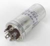
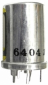
The most common type of high voltage can cap, especially in North American equipment was the twist-lock ("FP") type, made by Mallory, Sprague, Aerovox, and other U.S. manufacturers. Most have a base diameter of 1 3/8", but some are 1". They were made in many different heights. When selecting replacements, some important points should be noted:
Nearly all multi-section twist-lock can caps employ a common negative terminal, though there are some exceptions.
In most units the metal can is exposed and internally connected to common negative terminal, but again there are some exceptions. In applications where the negative terminal is not connected to "ground" or is not connected to the metal chassis, the capacitor will often have a layer of thick paper of plastic insulation to guard against contact with the chassis, and/or protect against shock. These insulated types must be replaced with similar units.
Twist-lock capacitors can be mounted with metal mounting wafers, or insulated fiber wafers. If the metal can is connected to the common negative terminal AND a metal mounting wafer is used, there will be a direct, low resistance connection between the negative pole of the capacitor and the chassis. This is the most common arrangement, but standard uninsulated can caps are sometimes installed with an insulated fiber washer, to isolate the negative pole from the chassis. An insulated can cap is should always be installed with an insulated fiber wafer.
All this may seem rather confusing, but the main point is that when replacing twist-lock can capacitors it is essential that you replace insulated capacitors with insulated types, and use the same type of mounting wafer as was originally installed. Also, when replacing twist-lock caps, the ground wires and jumper wires must be installed to EXACTLY match the original capacitor wiring. Otherwise, you may introduce hum or buzz. It's best to take a clear photo of the original capacitor and wiring before removing the old cap, and/or make a detailed drawing or notes. When installing the replacement cap, go back to your documentation, and try to make the new work look exactly the same.
The good news is that while mounting, insulation, and wiring details are critical, microfarad and voltage ratings are not. Replacement parts don't need to match the original specs closely, and there are some simple creative tricks for finding suitable replacement can caps when exact replacements aren't available. And in some cases, performance can be improved by making small changes.
Let's start with a simple example: replacement of one section can cap rated at 25 UF (MFD), 350 Volts (VDC). Does the original cap have an insulating cover, as opposed to an exposed metal can? That is rare and makes finding a proper replacement more difficult. But if the metal can is exposed (much more likely) note the diameter, and the voltage and capacitance ratings. Start by checking our stock of one section can caps. The diameter will be 1" or 1 3/8" and that parameter is critical, so disregard caps with the wrong diameter. In most cases the height is not critical and taller caps are fine, if there's enough clearance with the cover or cabinet in place. For the voltage and capacitance ratings you probably won't find exact matches, but it doesn't really matter -- just choose a cap with equal or greater ratings, within about a 50% range. So the 25 UF 350 VDC cap can be replaced with any unit rated at 25, 30, 35, or 40 UF, and a 350, 400, 425, 450, or 500 VDC, which gives you a lot of flexibility. Going with a higher voltage can increase reliability and working life; increasing capacitance reduces hum and buzz in some cases. (Note: in circuits with solid state rectifiers such as silicon diodes, bridge rectifiers, or selenium rectifiers, you shouldn't increase capacitance by more than about 25%, due turn on current considerations. Tube power supplies are more forgiving in this regard, and can generally tolerate up to a 100% increase.)
If you can't find a one section cap that meets your needs, that are still several good options. Browse our lists of two or three section caps. As long as the diameter, height, and voltage are suitable, you can add capacitance by wiring 2 or more sections in parallel. So for the example above, you could use a dual cap with 10 and 15 UF sections (or 15 and 15, 5 and 20, 10 and 20 15 and 20, etc,) by simply connecting the two terminals together. (The total capacitance of two or more capacitors in parallel is simply the sum of the individual capacitors.) You can also use a dual cap with a 25 UF or greater section, and a second section of any UF and voltage rating, leaving the second section un-wired. If you can't find a replacement with a high enough capacitance rating, you can also parallel a separate axial or radial cap under the chassis to achieve the total that you need. Our web store has a large selection of quality, high voltage axial and radial caps. INSERT LINK HERE So, the 25 UF 350 VDC cap in our original example could also be replaced with a 15 UF can cap, plus a 10 UF axial or radial cap under the chassis.
If you're replacing a multi section can cap, all the above guidelines still apply. Take the time to review the multi section caps that are available, and use your problem solving skills to locate a replacement unit that will work. If you can't find a can cap that includes all the sections you need, maybe you can find unit that replaces all the sections you need except one, and install an axial or radial cap under the chassis to cover the missing section
With a little creative searching and substitution, a suitable replacement solution can be found for almost any type of can capacitor. Our shop restores lots of vintage gear, and in 99% of cases we are able to replace original can caps without re-stuffing. You can do it, too.
Some other notes and hints:
• In vintage tube gear, guitar amps, etc. the most common can cap voltage is 450 VDC; the most common capacitance ratings are 20 and 40 UF. We stock high quality new 4 section German made can caps with four 50 UF sections, each rated at 500 VDC, that are 1 3/8" in diameter; http://www.studioelectronics.biz/sunshop/index.php?l=product_detail&p=1498. These are perfect in a wide variety of applications. The 500 volt rating makes them excellent replacements for caps rated between 350 and 500 VDC, and the four 50 UF sections can be combined in many ways or used as "rounded" up replacements for values under 50 UF.
• Some late model tube equipment with printed circuit boards (and some early solid state gear) used a special type of can cap that mounted directly to the PC board. As of early 2014 we have a few can caps of this type in stock, but in general they are very hard to find. In these cases the best options are usually re-stuffing the original can, or installing axial or radial caps. In the latter case, foils to the positive terminals of the original cap should be cut.
• Other styles of can caps are "computer grade" types, usually fastened to the top of a chassis with a round mounting ring, and stud mount types which mount with a large threaded bushing. Generally these caps have working voltages of 100 VDC or less, capacitance ratings of 5000 UF or more, and screw terminals on the top. We have some of these types listed on our web store.
• Some of these can caps include a metal mounting wafer, some include a fiber wafer, some include no wafer. If you need a mounting wafer, please add a note to your order telling us which type you’d like, and we’ll try to include it.
• Please note: Mallory parts with the prefix TC are dual metal tubular types with an insulating sleeve, meant to be mounted under a chassis.